Product Overview
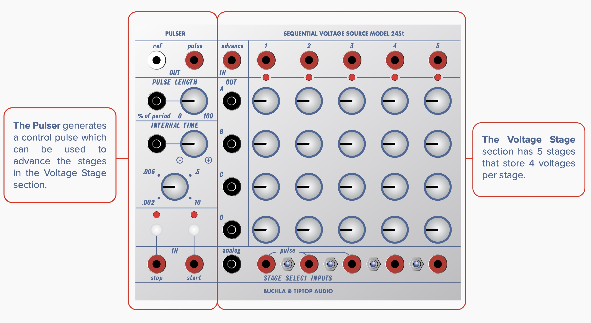
Buchla 245t has two sections: Pulser and Stored Voltage Stages.
The Pulser generates a control pulse which can be used to advance the stages in the Voltage Stage section.
The Voltage Stage section has 5 stages that store 4 voltages per stage.
Pulser Section:
Pulse - output generates a pulse with a 10V initial stage that lasts for 100uSec (0.1ms) followed by a 5V gate stage length determined by the Pulse Length control.
Ref - outputs a ramp wave that descends from 10V to 0V at the rate of the pulser.
Pulse Length - sets the length of the 5V stage of the pulse from 0 to 100% of the duty cycle. External CV control is added to the knob setting.
Internal Time - controls the period of the pulser output from 10 seconds (full CW) to a few milliseconds (full CCW). External CV has an attenuverted control to either add (CW) or subtract (CCW) external voltage from the knob setting. External CV can increase the maximum and minimum period of the pulser to approximately 50 seconds to 1ms (1kHz) (*).
Start - Pressing this button starts generating a pulse and reference ramp at those outputs. A pulse on the Start input also begins pulser generation.
Stop - Pressing the button or sending a pulse to the input jack stops the pulser if already running. Additional presses or pulses to the Stop input will manually trigger a single pulse output from the pulser.
Stored Voltage Stages:
Advance In - accepts a pulse from the Pulser or external source (281t EOC for example) and each pulse advances to the next stage from 1 to 5. The switches in the Stage Select section can control the number of stages played back.
Note, with all stage switches in down position playback will be on hold.
Stage Gate Output - Each stage has a dedicated gate output that OUT produces a high voltage (10V) when that stage is active. This gate can be used to trigger events like envelopes.
Out - the voltage output of the current active stage.% of Each of0 the period outputs has an independent voltage.
Stored Voltages - 4 rows of 5 locations of stored analog voltages set by a control knob.
Analog (In) - CV input (0-10V) that addresses the stages. When the voltage is above the Off range the Analog input is active and the Advance and Stage Select Inputs are disabled.
Ranges are approximately(*): Off (0V - 0.75V), Stage 1 (0.75V - 2.5V) Stage 2 (2.5V to 4.25V) Stage 3 (4.25V to 6V) Stage 4 (6V to 7.75V) Stage 5 (7.75V to 10V)
Stage Select Inputs - Pulses on these 5 inputs will immediately set the active Stage to the corresponding input. Using these inputs can create a type of analog preset memory for 4 CV settings in your modular system.
Stage Switches - These 4 switches enable or disable the stage transitions. Switch 1 controls Stage 1 to 2 transition, switch 2 Stage 2 to 3 and so on. By disabling a stage transition the length of the sequence can be shortened or captured.
* Note: due to the analog nature of the design specifications for pulser timing and length and Analog In will slightly vary from unit to unit.
Specifications:
Ref Out 0 - 10V
Pulser Out 0 to 10V
Pulse Length CV 0 - 10V
Internal Time CV 0 - 10V
Start Pulse In 0 - 10V
Stop Pulse In 0 - 10V
Advance In 0 - 10V
Analog In 0 - 10V
Stage Select In 0 - 10V
Stored Voltage Out 0 - 10V
Stage Gate Out 0 - 10V
Size: 30HP - Depth: 25mm
Power: +12V 63mA / -12V 28mA


